English
Views: 0 Author: Site Editor Publish Time: 2026-06-16 Origin: Site
Specifying high-performance solid-liquid separation equipment represents only half the engineering battle. Integrating it properly into an existing facility dictates its long-term operational viability. A brilliant mechanical design fails entirely if plant technicians cannot physically reach the moving components. Unfortunately, poor layout decisions directly lead to restricted maintenance access across the plant floor. They also create highly inefficient piping runs. These poorly planned pipe runs cause severe pressure drops. Consequently, operators face prolonged, frustrating downtime during routine cloth replacements.
To solve this, we provide a realistic framework for optimizing a vacuum belt filter layout. You will learn how to strategically balance rigid footprint constraints and complex fluid routing requirements. We will also outline critical access clearances necessary to ensure seamless operations. Proper planning prevents catastrophic mechanical failures. It also keeps your maintenance team safe while reducing unnecessary labor hours.
Frame Customization: Choosing between pre-welded (faster installation) and bolted modular frames (for restricted access) fundamentally dictates initial footprint and staging space.
Piping Complexity: Countercurrent wash setups significantly reduce water consumption but require stacked, multi-stage piping networks that demand careful vertical layout planning.
Maintenance Clearances: Designing physical space for visual inspection (e.g., light transmission tests, spotting "wet lines" on the cake) and automated tracking systems prevents catastrophic belt failure.
Vacuum Box Access: Opting for pneumatic lifting devices over traditional counterweight systems changes the under-machine clearance requirements for seal and friction belt maintenance.
Choosing the right structural frame design represents your first major project milestone. You face a distinct trade-off between installation speed and staging space. Fully pre-welded frames drastically reduce on-site assembly time. They can cut field installation hours by up to 80 percent. However, they demand massive staging areas and extremely wide plant doors. You need heavy overhead cranes to maneuver these rigid structures into place.
Conversely, modular bolted frames offer incredible physical flexibility. These heavy-duty frames remain mandatory for older facilities. You must use them when navigating existing tight corridors. Bolted designs take longer to assemble on the floor. Yet, they bypass the need to demolish exterior walls for equipment entry. You bolt them together piece by piece in tight areas.
Your deck support system heavily influences vertical space and overall structural height. Different belt support mechanisms impact the ancillary equipment footprint significantly. You must evaluate three primary deck styles for your operation.
Roller Decks: These systems provide inherently lower mechanical friction. They completely remove the need for high-pressure air blowers. This choice saves valuable floor space around the filtration unit. It also reduces ambient noise levels on the plant floor.
Air Cushion (Air Box) Systems: This setup requires dedicated space for external blowers. You must route large-diameter air ducts directly to the machine. However, it provides optimal frictionless support for heavy filter cakes exceeding 20-25 millimeters in thickness.
Water Slide Rails: These offer a much lower mechanical profile. You must design robust water collection routing below the machine. They consume more continuous lubrication water but feature fewer moving parts.
Fluid routing dictates how efficiently your machine processes industrial slurries. We must optimize the feed zone architecture first. Consider layout clearances for backward feeding mechanisms. These systems direct the incoming slurry against the belt travel direction. This approach optimizes natural settling dramatically. Larger particles fall first, creating a permeable pre-coat layer. This protects the cloth from fine particle blinding. However, backward feeding requires specific overhead clearance at the tail pulley. You must accommodate much larger feed box dimensions.
Next, evaluate your wash system piping layout carefully. You generally choose between cocurrent and countercurrent washing designs. Each dictates a radically different piping footprint above and below the machine.
Cocurrent washing offers a simpler manifold layout. It demands much lower spatial requirements directly above the filter cloth. Water flows once through the cake and discharges immediately. Countercurrent washing proves highly efficient for strict water conservation. It directs wash fluid opposite to the solid cake travel. It demands complex, multi-stage cascading pipework. You must plan for intermediate wash-water collection tanks. These tanks sit directly within the overall frame footprint.
Wash System Type | Layout Complexity | Vertical Space Required | Water Conservation |
|---|---|---|---|
Cocurrent | Low | Minimal (Single Manifold) | Standard |
Countercurrent | High | Significant (Stacked Pipes & Tanks) | Excellent |
Your vacuum routing directly impacts dewatering efficiency and power consumption. Position the vacuum pump and associated gas-water separators carefully. Place them as close to the main unit as practically possible. Short, direct pipes mitigate harmful vacuum pressure drops. A common layout mistake involves placing pumps in distant utility rooms. This forces long pipe runs resulting in massive energy losses. Furthermore, ensure the central drainage zone has uninterrupted gravity flow. Filtrate must travel downward to the receivers without artificial bottlenecks. If you use a barometric leg for separation, remember it requires at least 10 meters of vertical downward clearance.
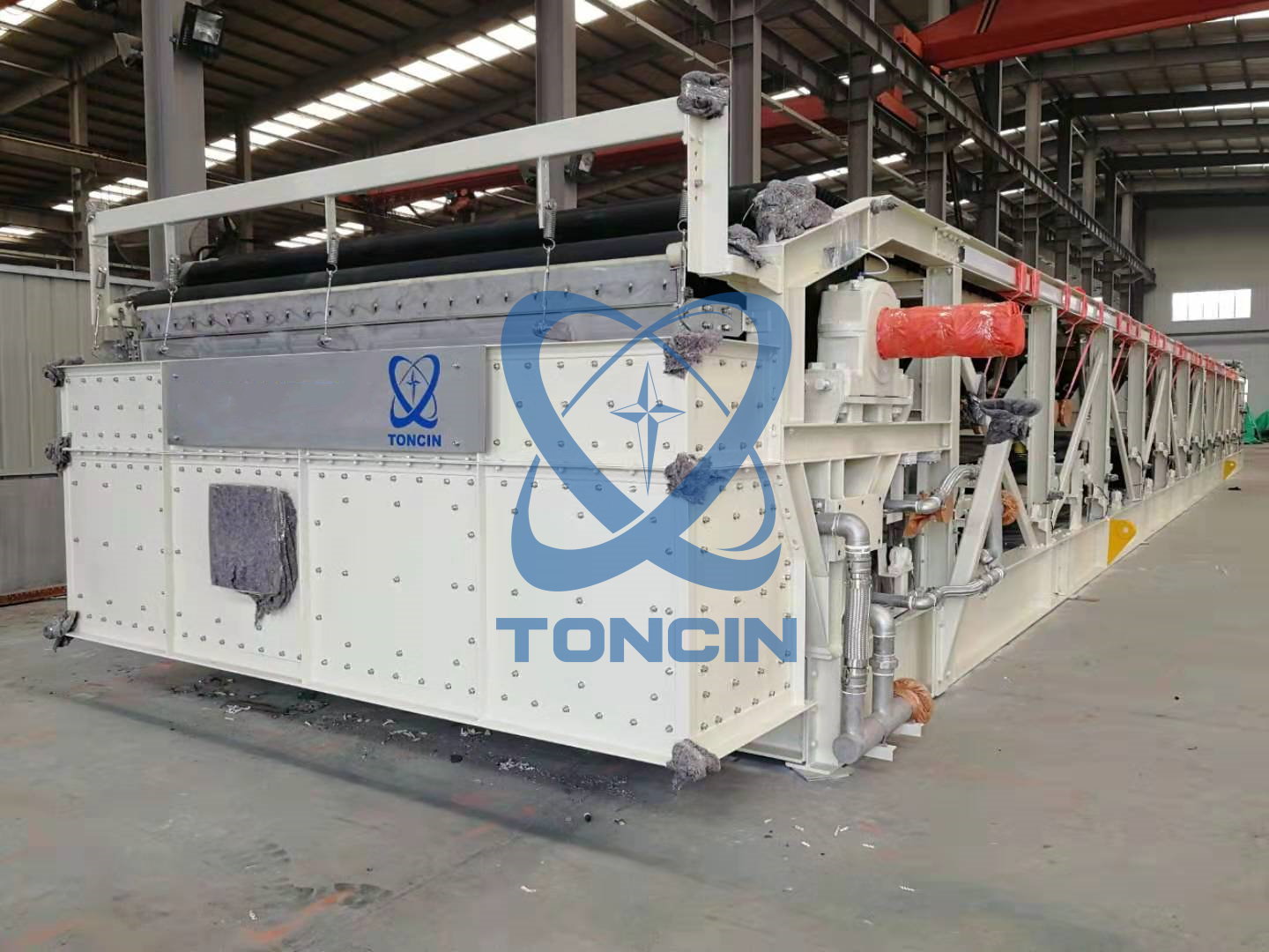
An open-design layout around your vacuum belt filter is completely non-negotiable. Ensure your operators have a clear line-of-sight to the discharge end. They must easily view the central seams during active operation. This visual access allows them to spot "wet lines" or "moist strips" on the discharging cake. These vertical marks clearly indicate localized cloth blinding or physical damage. If operators cannot see the cake, small tears become catastrophic failures quickly.
You must leave adequate physical clearance directly under the discharge roller. Technicians absolutely need this space to conduct light-transmission damage inspections. They perform these critical diagnostic checks during scheduled plant downtime. A technician shines a bright light from below the cloth. Another technician observes from above to spot pinhole leaks. A cramped facility layout makes this simple preventative test impossible.
Furthermore, you must allocate generous space for tracking systems. Reserve ample side-clearance for the mechanical action valves. Leave room for the pneumatic airbags used in automated filter cloth deviation correction systems. The cloth touches a sensor paddle when it drifts. This paddle opens a pneumatic valve. The airbag inflates, shifting the steering roll back into alignment. If you cramp these sensitive components against a wall, automatic tracking fails completely.
Additionally, evaluate the feed-end tensioning pulleys during your layout phase. Ensure they have sufficient longitudinal travel space. They must accommodate gradual belt elongation over time. Heavy rubber belts stretch naturally under immense vacuum forces. Proper travel space delays cloth replacement until absolutely necessary. A common layout mistake restricts this travel distance, forcing premature and expensive belt swaps.
Under-machine clearances depend heavily on your chosen lifting mechanisms. We must compare traditional counterweight designs against modern pneumatic lifting systems. Traditional systems utilize bulky mechanical counterweights. These heavy steel blocks require significant swing clearance below the machine frame. They pose severe safety hazards if personnel walk too closely during operation. You must fence off large zones beneath the equipment.
Conversely, modern pneumatic vacuum box lifting systems remain much more compact. They offer automated, constant-pressure compensation for wear belt degradation. They keep the vacuum seal tight automatically as friction components slowly wear down. However, they require integrated compressed airline routing. You must plan for these flexible air hoses during the initial piping design phase to avoid tangles.
Your physical plant layout must allow technicians direct lateral access. They must reach the central vacuum chamber easily and safely. They routinely replace sacrificial friction belts in this tight central zone. They also maintain the automatic lubrication systems. These critical lubrication headers ensure the continuous water seal remains completely intact. Restricting lateral access turns a standard two-hour maintenance job into a multi-day ordeal. Always provide at least one full meter of clear walking space alongside the entire vacuum box length.
We strongly recommend using an evaluation matrix before finalizing your floor plan. This structured engineering approach prevents costly structural redesigns later in the project. You must review several critical layout criteria before pouring concrete.
Consider the capital expense versus operating expense balance regarding drive pulley selection. Ask yourself if the spatial layout allows for a large-diameter drive pulley. Large pulleys require a slightly larger structural footprint at the discharge end. However, they utilize lower motor power to achieve higher rotational torque. This clever mechanical geometry yields significant long-term energy savings.
Next, plan carefully for overload prevention instrumentation. The layout must accommodate precise differential pressure monitoring instruments. Position them in easily accessible, readable locations at eye level. They trigger critical control system alerts when pressure reaches 0.5 to 1 kg/cm². Immediate access to these sensors prevents hydraulic system overheating and subsequent mechanical failure.
Finally, analyze your solid discharge logistics thoroughly. Ensure the discharge end seamlessly integrates downward into your continuous process flow. It must align perfectly with downstream conveyors or cake collection hoppers. Poor alignment creates dangerous material choke points. Avoid sharp vertical drops or shallow angled chutes. Sticky filter cakes bridge easily in poorly designed transitions. A well-planned belt filter layout always accounts for the physical trajectory of the falling cake.
Evaluation Criteria | Layout Consideration | Primary Benefit |
|---|---|---|
Drive Pulley Sizing | Allocate extra space for large-diameter pulleys at the discharge end. | Reduces required motor power and increases energy efficiency. |
Instrument Placement | Mount pressure monitors (0.5-1 kg/cm² range) at eye level. | Prevents unnoticed hydraulic overheating and system overloads. |
Discharge Alignment | Ensure straight downward trajectory into hoppers or conveyors. | Eliminates material bridging and dangerous choke points. |
Achieving a successful equipment installation requires strategic engineering compromise. You must carefully balance ideal engineering geometry against actual plant floor realities. Perfection on paper often requires practical, field-level adjustments. We want to ensure your operations remain efficient and safe for decades.
Here are your recommended next steps:
Conduct a comprehensive 3D spatial audit of the entire facility space before selecting frame types.
Map out complex wash configurations and piping runs using specialized 3D modeling software to avoid clashing.
Verify all lateral access zones meet your internal maintenance safety requirements.
Engage directly with applications engineers to run a custom footprint simulation based on your specific daily capacity.
A: A minimum of 1 to 1.5 meters on both sides is generally recommended. This spacing allows ample access for belt replacement. It also provides room for automated tracking device calibration. Furthermore, it ensures operators can conduct thorough visual inspections of the filter cloth without physical obstruction.
A: Yes, it absolutely does. The physical size and type of the vacuum pump dictate a significant portion of the footprint. Liquid ring pumps require seal water tanks and gas-liquid separators. Dry pumps need specific silencers. You must accommodate this ancillary equipment and its associated piping nearby.
A: Countercurrent washing moves the wash fluid in the opposite direction of the cake travel. This highly efficient process requires staging multiple collection pans. It also involves recirculation pumps and complex overhead spray manifolds. Consequently, it significantly increases the vertical and internal spatial footprint of the equipment.
A: Traditional systems use bulky mechanical counterweights that require wide swing clearance below the machine. In contrast, modern pneumatic lifting devices are much more compact and highly reliable. They eliminate large moving weights, freeing up critical under-machine space. This allows for cleaner filtrate piping routing and safer maintenance access.