 English

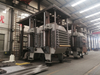


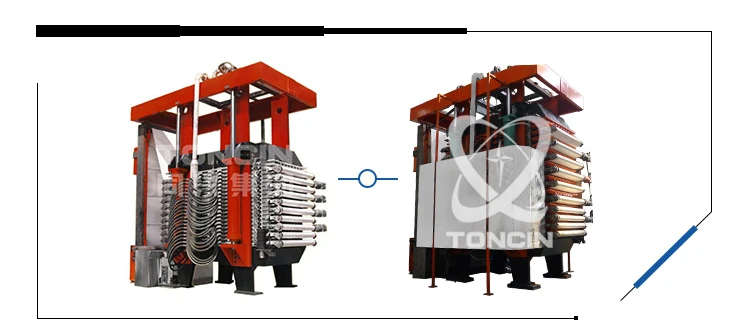
HVPF vertical automatic press filter is the most advanced filter that the world has ever get. Vacuum has a limit, but Pressure not. HVPF vertical automatic press filter use air or water to form a huge pressure difference on both sides of filter cloth to achieve very efficient separation of solid and liquid.
| Quantity: | |
|---|---|


HVPF Filter Press
Toncin
Product Introduction:
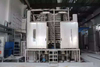
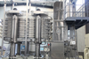
The HVPF vertical automatic filter press represents the pinnacle of filtration technology. While vacuum-based filtration has inherent limitations, pressure-driven separation offers far greater potential. The HVPF system utilizes highly pressurized air or water to generate an extreme pressure differential across the filter cloth, enabling exceptionally efficient solid-liquid separation.
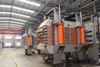
Here's how it works: once the filter plates are securely closed, slurry is pumped into the filtration chambers. An initial amount of filtrate drains by gravity through the cloth into the collection system. Next, high-pressure water is introduced to expand rubber diaphragms, which mechanically compress the filter cake and express residual liquid. Upon completion of the cycle, the drive mechanism activates to move the filter cloth, discharging the solid cake from both sides of the press automatically.
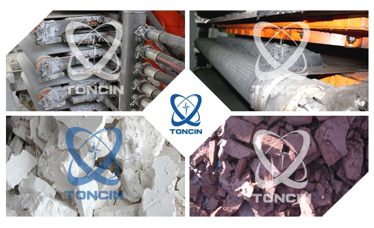
Product Application:
The HVPF vertical automatic filter press is a high-capacity, energy-efficient solution for solid-liquid separation, suitable for a wide range of industries including mining, metallurgy, chemicals, pharmaceuticals, and food processing.
Supply Range and Requirements on Local Installation:
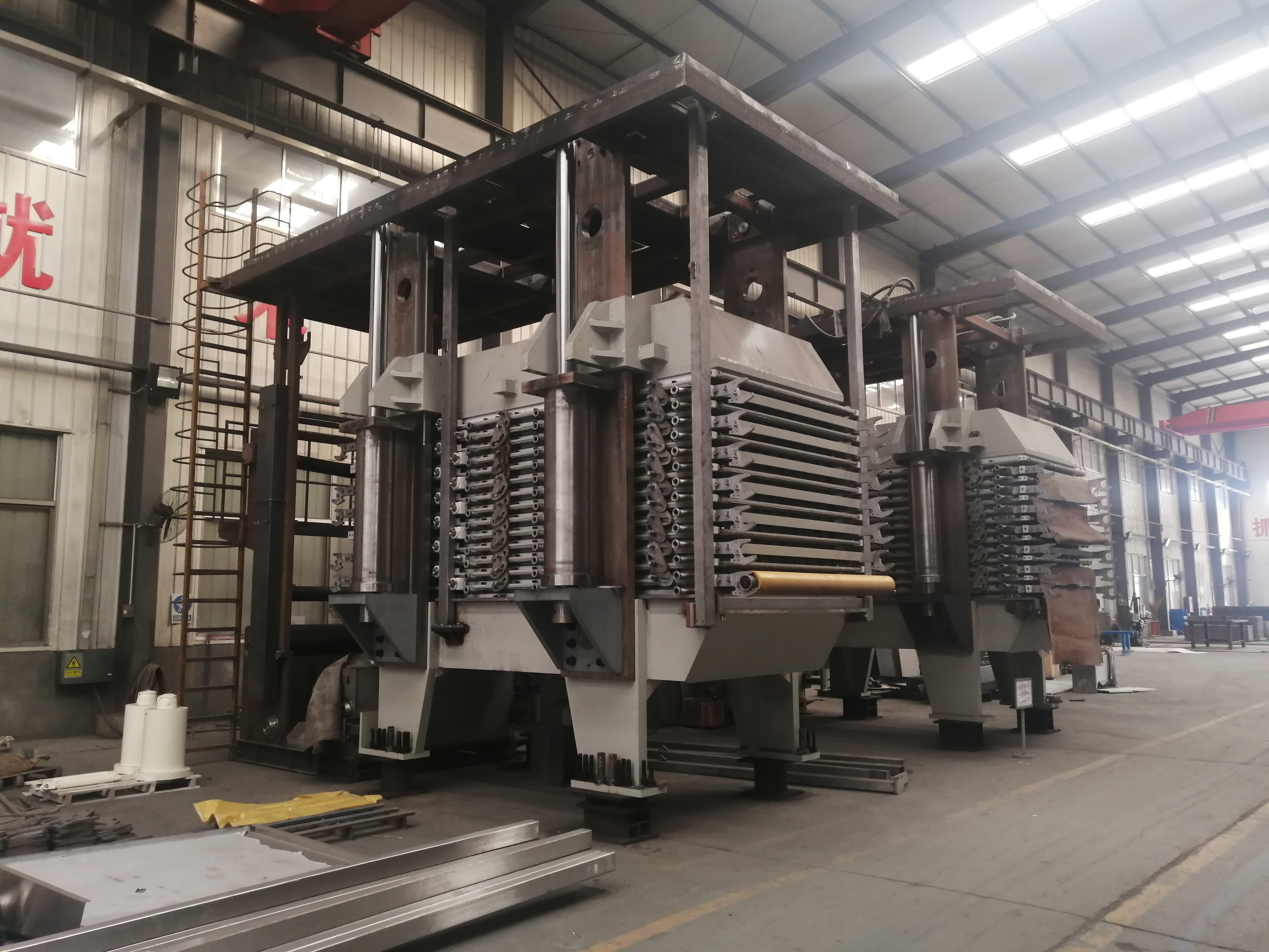
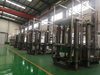
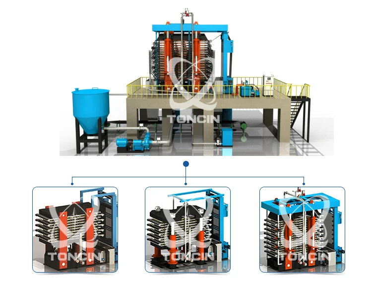
The HVPF vertical automatic filter press system comprises the following major components: the main unit, hydraulic power pack, water station, cleaning system, and a central control system.
(1) Installation Foundation
The equipment must be installed on a solid, level reinforced concrete base or a steel structure frame. Please refer to the installation diagram and foundation plan for specific dimensions and requirements. The foundation depth should be determined by the customer based on local soil conditions.
The main unit must be hoisted and positioned by qualified personnel to prevent impact or surface damage. During installation, use precision leveling instruments to adjust the host to the correct position before securing it. Ancillary equipment can then be installed and aligned accordingly.
(2) Compressed Air Supply
Air Quality: Oil-free, with particles ≤ 5 µm
Pressure: 0.5 - 0.6 MPa
Flow Rate: Refer to the assembly diagram for required volume
(3) Water Supply
Maximum Solid Content: ≤ 5 ppm
Particle Size: ≤ 50 µm
Pressure: 3.5 - 6 bar
Flow Rate: Refer to the assembly diagram for required volume
(4) Power Supply
3-Phase: 380V ± 5%, 50Hz
1-Phase: 220V ± 5%, 50Hz
(5) Operating Environment
The equipment must be installed in a frost-free environment. All other ambient conditions should comply with standard industrial operational requirements.
Product Specifications:
Model
| Filtrating Area(m2) | Overall Dimension m (L×W×H) | Filtrating Plate Quantity | Volume(m3) | Weight (T) | Hydraulic power (KW) | Filter plate specification (mm) | Width of filter cloth |
HVPF-1 | 1 | 2.5×1.5×2.0 | 2 | 0.05 | 8 | 7.5 | 1000*550 | 0.7 |
HVPF-2 | 2 | 2.5×1.5×2.2 | 4 | 0.09 | 9 | 7.5 | ||
HVPF-3 | 3 | 3.5×2.5×2.2 | 2 | 0.16 | 14 | 11 | 1750*900 | 1.05 |
HVPF-4 | 4 | 3.5×2.5×2.3 | 4 | 0.27 | 15 | 11 | ||
HVPF-9 | 9 | 3.5×2.5×2.5 | 6 | 0.41 | 16 | 11 | ||
HVPF-12 | 12 | 3.5×2.5×2.7 | 8 | 0.54 | 17 | 11 | ||
HVPF-15 | 15 | 3.5×2.5×2.9 | 10 | 0.68 | 18 | 11 | ||
HVPF-18 | 18 | 3.5×2.5×3.1 | 12 | 0.81 | 19 | 11 | ||
HVPF-21 | 21 | 3.5×2.5×3.3 | 14 | 0.95 | 21 | 11 | ||
HVPF-24 | 24 | 3.5×2.5×3.4 | 16 | 1.08 | 22 | 11 | ||
HVPF-27 | 27 | 3.5×2.5×3.6 | 18 | 1.22 | 23 | 11 | ||
HVPF-15 | 15 | 5.1×3.7×3.3 | 6 | 0.68 | 37 | 22 | 2500*1020 | 1.15 |
HVPF-20 | 20 | 5.1×3.7×3.6 | 8 | 0.9 | 39 | 22 | ||
HVPF-25 | 25 | 5.1×3.7×3.9 | 10 | 1.13 | 42 | 22 | ||
HVPF-30 | 30 | 5.1×3.7×4.2 | 12 | 1.35 | 43 | 22 | ||
HVPF-35 | 35 | 5.1×3.7×4.5 | 14 | 1.58 | 44 | 22 | ||
HVPF-40 | 40 | 5.1×3.7×4.8 | 16 | 1.8 | 45 | 22 | ||
HVPF-45 | 45 | 5.1×3.7×5.1 | 18 | 2.03 | 46 | 22 | ||
HVPF-50 | 50 | 5.1×3.7×5.4 | 20 | 2.25 | 48 | 22 | ||
HVPF-60 | 60 | 6.9×4.5×5.4 | 10 | 2.7 | 97 | 37 | 4010*1500 | 1.7 |
HVPF-72 | 72 | 6.9×4.5×5.8 | 12 | 3.24 | 100 | 37 | ||
HVPF-84 | 84 | 6.9×4.5×6.2 | 14 | 3.78 | 104 | 37 | ||
HVPF-96 | 96 | 6.9×4.5×6.5 | 16 | 4.32 | 110 | 37 | ||
HVPF-108 | 108 | 6.9×4.5×6.9 | 18 | 4.86 | 112 | 37 | ||
HVPF-120 | 120 | 6.9×4.5×7.2 | 20 | 5.4 | 118 | 37 | ||
HVPF-132 | 132 | 6.9×4.5×7.6 | 22 | 5.94 | 120 | 37 | ||
HVPF-144 | 144 | 6.9×4.5×7.9 | 24 | 6.48 | 123 | 37 | ||
HVPF-156 | 156 | 6.9×4.5×8.3 | 26 | 7.02 | 126 | 37 | ||
HVPF-168 | 168 | 6.9×4.5×8.6 | 28 | 7.56 | 130 | 37 | ||
HVPF-144 | 144 | 9.2×5.5×6.8 | 18 | 6.48 | 142 | 67 | 6020*1500 | 1.7 |
HVPF-162 | 162 | 9.2×5.5×7.2 | 18 | 7.29 | 147 | 67 | ||
HVPF-180 | 180 | 9.2×5.5×7.5 | 20 | 8.1 | 150 | 67 | ||
HVPF-198 | 198 | 9.2×5.5×7.8 | 22 | 8.91 | 160 | 67 | ||
HVPF-216 | 216 | 9.2×5.5×8.2 | 24 | 9.72 | 166 | 67 | ||
HVPF-234 | 234 | 9.2×5.5×8.5 | 26 | 10.53 | 172 | 67 | ||
HVPF-252 | 252 | 9.2×5.5×8.8 | 28 | 11.34 | 180 | 67 | ||
HVPF-270 | 270 | 9.2×5.5×9.2 | 30 | 12.15 | 190 | 67 |
Working Process:
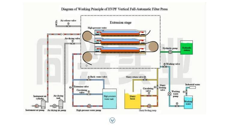
The filtration process consists of the following five stages:
Filtration Stage
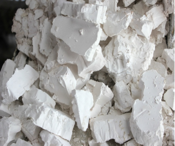
Once the filter plates are closed, slurry is pumped into the chambers via the feed pipe. The filtrate passes through the filter cloth, enters the collection chamber, and is discharged through the manifold. Simultaneously, solid material accumulates within the chambers, forming the filter cake.
Membrane Squeeze Stage
High-pressure water is introduced into the membrane plates, causing the membranes to expand and apply uniform mechanical pressure to the filter cake. This action significantly reduces the cake moisture by expressing additional filtrate.
Cake Washing (Optional)
Washing liquid is pumped through the same feed distribution system to permeate the filter cake. The spent wash liquor passes through the cloth and is discharged separately via the designated outlets.
Air Blow-Drying
Compressed air is introduced to pass through the cake, displacing residual moisture and further reducing the cake's liquid content. This step also helps clear any remaining filtrate from the discharge system.
Cake Discharge
Upon completion of the cycle, the drive mechanism moves the filter cloth, causing the solid filter cake to be cleanly and automatically discharged from both sides of the filter.
The structure of filter plate adopts guide device to make sure the smoothly running.
It can continuously automatically realize the operation in the process of filtering, extrusion, washing, drying, discharging and filter cloth regeneration.
The filter pressure can reach 2.0 Mpa. Especially have good effect on various sticky tiny materials and low moisture of filter cake.
the key point of this type of equipment is no matter how much pressure it can get but safety. Hydraulic pressure system is adopted just to make sure every plate locks well. Every nozzle and diaphragm are designed and inspected very carefully to keep the equipment safe when high pressure water gets into chambers.
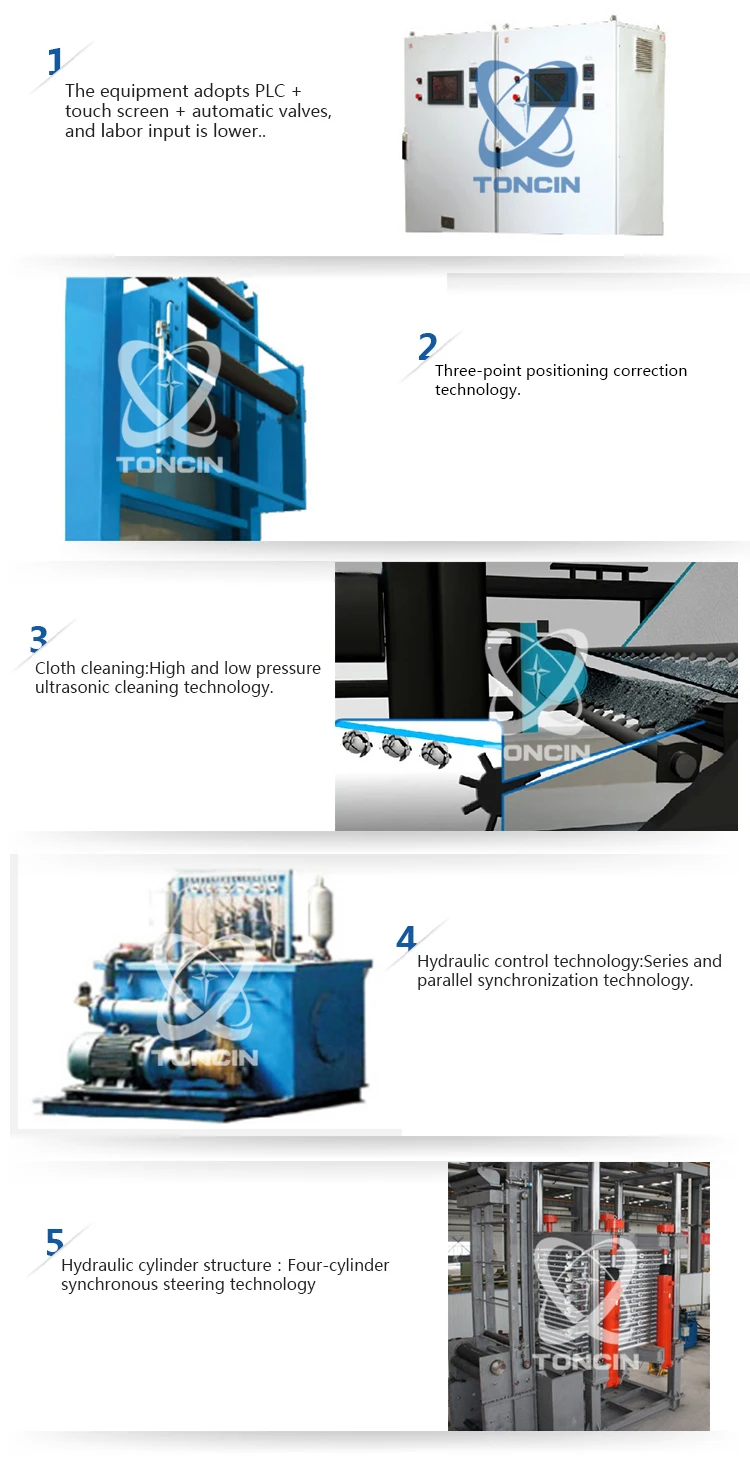
The equipment adopts PLC + touch screen + automatic valves, and labor input is lower..
Compact structure covers less floor area
Service Support
Whole Technological Design
Toncin determines reasonable plans and selections by conducting more systematic laboratory tests, semi-industrialization tests and theoretical analysis calculations and adopting appropriate methods in light of the actual problems faced by customers. And it determines specific parameters through laboratory tests and semi-industrial tests.
Project Construction
Toncin can provide customers with integrated project services for its perfect project management system and experienced high-quality team and can also provide customers with its best services in achieving the ultimate project goal by carrying out the management work on the project quality, schedule, safety, cost, procurement, information files, organization and coordination etc. according to customer’s contractual documents. Toncin contracts the design, procurement, construction and trials etc. for the entire process or some certain stages of the construction project according to the contract and takes full liability for the quality, safety, duration and cost etc. of the contracted project.
Response Time and After-sales Services
If any failure due to a defect has occurred during the warranty period, our company has given the following response and promise: to respond within 12 hours and rush to the domestic scene within 72 hours. With a rigorous and efficient service architecture, diverse and flexible service and response means, Toncin is capable of providing response service up to 7* 24 hours to ensure that users can get help at any time during the warranty period.


